| [pending review revision] | [pending review revision] |
(Page créée avec « Longueur de la fibre à identifier ») |
(Page créée avec « Le localisateur peut être utilisé sur des liens allant jusqu'à 10 km. Au delà, quelque soit la puissance d'un crayon optique, le faisceau lumineux ne peut pas être pe... ») |
||
| Line 52: | Line 52: | ||
{{Tuto Step | {{Tuto Step | ||
|Step_Title=Longueur de la fibre à identifier | |Step_Title=Longueur de la fibre à identifier | ||
| − | |Step_Content= | + | |Step_Content=Le localisateur peut être utilisé sur des liens allant jusqu'à 10 km. Au delà, quelque soit la puissance d'un crayon optique, le faisceau lumineux ne peut pas être perçu. |
|Step_Picture_00=Visual_location_of_defects_on_optical_fiber_img96.jpg | |Step_Picture_00=Visual_location_of_defects_on_optical_fiber_img96.jpg | ||
|Step_Picture_00_annotation={"version":"2.4.6","objects":[{"type":"image","version":"2.4.6","originX":"left","originY":"top","left":-201,"top":-1,"width":800,"height":425,"fill":"rgb(0,0,0)","stroke":null,"strokeWidth":0,"strokeDashArray":null,"strokeLineCap":"butt","strokeDashOffset":0,"strokeLineJoin":"miter","strokeMiterLimit":4,"scaleX":1.07,"scaleY":1.07,"angle":0,"flipX":false,"flipY":false,"opacity":1,"shadow":null,"visible":true,"clipTo":null,"backgroundColor":"","fillRule":"nonzero","paintFirst":"fill","globalCompositeOperation":"source-over","transformMatrix":null,"skewX":0,"skewY":0,"crossOrigin":"","cropX":0,"cropY":0,"src":"http://demo-master.dokit.io/w/images/2/27/Visual_location_of_defects_on_optical_fiber_img96.jpg","filters":[]}],"height":450.2970297029703,"width":600} | |Step_Picture_00_annotation={"version":"2.4.6","objects":[{"type":"image","version":"2.4.6","originX":"left","originY":"top","left":-201,"top":-1,"width":800,"height":425,"fill":"rgb(0,0,0)","stroke":null,"strokeWidth":0,"strokeDashArray":null,"strokeLineCap":"butt","strokeDashOffset":0,"strokeLineJoin":"miter","strokeMiterLimit":4,"scaleX":1.07,"scaleY":1.07,"angle":0,"flipX":false,"flipY":false,"opacity":1,"shadow":null,"visible":true,"clipTo":null,"backgroundColor":"","fillRule":"nonzero","paintFirst":"fill","globalCompositeOperation":"source-over","transformMatrix":null,"skewX":0,"skewY":0,"crossOrigin":"","cropX":0,"cropY":0,"src":"http://demo-master.dokit.io/w/images/2/27/Visual_location_of_defects_on_optical_fiber_img96.jpg","filters":[]}],"height":450.2970297029703,"width":600} | ||
Revision as of 15:50, 7 June 2019


Contents
- 1 Items
- 2 Step 1 - Règle de sécurité
- 3 Step 2 - Allumage et paramétrage
- 4 Step 3 - Raccordement sur la fibre
- 5 Step 4 - Longueur de la fibre à identifier
- 6 Step 5 - Step 5 - Locating the end
- 7 Step 6 - Step 6 - Locating the defect (a curve for example)
- 8 Step 7 - Step 7 - Turn off the device
- 9 Comments
- Items
Items

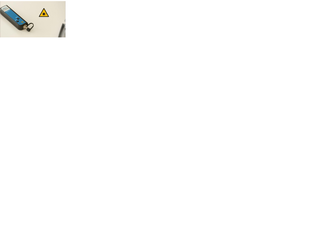
Step 1 - Règle de sécurité
Le localisateur visuel de défauts (ou crayon optique) émet une lumière rouge à une puissance de sortie de 10 mW. Ne pas visualiser directement le faisceau lumineux ou le diriger vers une autre personne. Replacer systématiquement le bouchon de protection après usage.
N'allumer l'appareil que lorsque le bouchon de protection est en place ou qu'un connecteur est fixé sur la sortie.

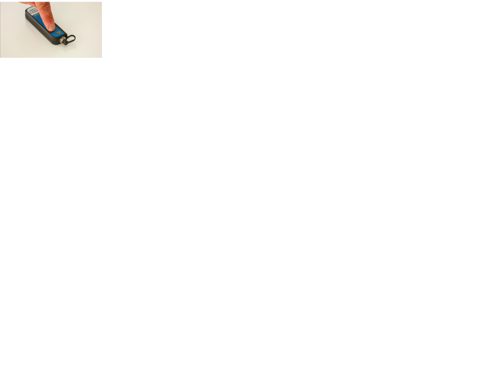
Step 2 - Allumage et paramétrage
Appuyer sur le bouton PWR. Le localisateur émet un signal continu ou pulsé selon le paramétrage choisi avec le bouton MOD.
Step 3 - Raccordement sur la fibre
Le localisateur visuel de défauts est compatible avec toutes les connectiques avec férule de 2,5 mm. Pour les férules de 1,25 mm, l'usage d'un adaptateur est nécessaire.


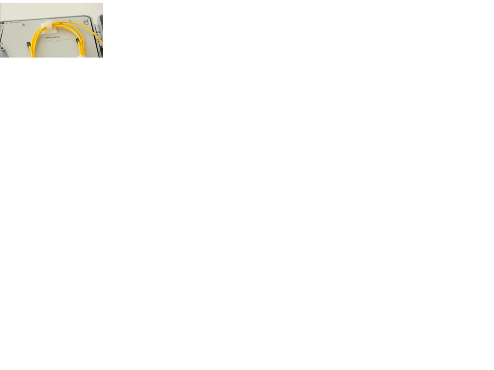
Step 4 - Longueur de la fibre à identifier
Le localisateur peut être utilisé sur des liens allant jusqu'à 10 km. Au delà, quelque soit la puissance d'un crayon optique, le faisceau lumineux ne peut pas être perçu.

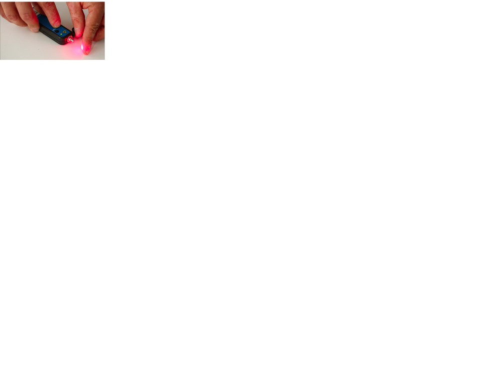
Step 5 - Step 5 - Locating the end
The end of an optical link is detected by the presence of the light signal. This is a function widely used for mixing garters in street cabinets or bays.

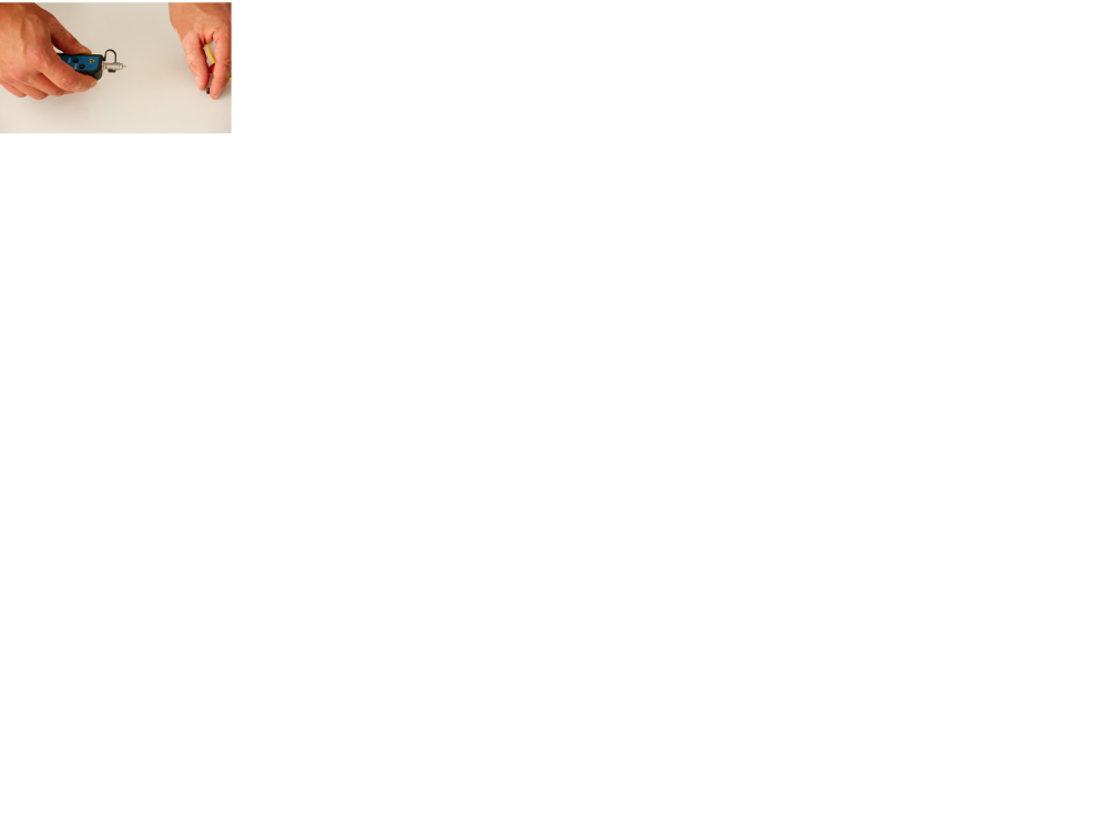
Step 6 - Step 6 - Locating the defect (a curve for example)
Due to the high reflection of the light as it passes through a stress (macro-curve) or when a fibre is cut, this device is widely used to correct defects (which cause significant optical losses), on the visible part of the fibres.


Step 7 - Step 7 - Turn off the device
After using the device, turn off the locator and place the protective cap on the optical output.

Published
 Français
 English
 Deutsch
 Español
 Italiano
 Português