| [pending review revision] | [pending review revision] |
(Page créée avec « Positionner la fibre dans la rainure adaptée du guide fibre (250 ou 900 µm), la gaine 250 ou 900 µm à la graduation 10 en faisant attention que la partie dénuée pren... ») |
(Page créée avec « Positionnement de la fibre dans la soudeuse ») |
||
| Line 50: | Line 50: | ||
}} | }} | ||
{{Tuto Step | {{Tuto Step | ||
| − | |Step_Title= | + | |Step_Title=Positionnement de la fibre dans la soudeuse |
|Step_Content=Position the fibre in the fusion splicer by placing its end between the alignment of the electrodes and the edge of the V-slot, close the valve retaining the fibre. | |Step_Content=Position the fibre in the fusion splicer by placing its end between the alignment of the electrodes and the edge of the V-slot, close the valve retaining the fibre. | ||
Revision as of 16:30, 7 June 2019

Contents
- 1 Items
- 2 Step 1 - Préparation des accessoires
- 3 Step 2 - Dénudage et nettoyage de la fibre
- 4 Step 3 - Clivage de la fibre
- 5 Step 4 - Positionnement de la fibre dans la soudeuse
- 6 Step 5 - Choosing the programs of the welder machine
- 7 Step 6 - Welding process
- 8 Step 7 - Welding evaluation
- 9 Step 8 - Positioning the smoove and shrinkage
- 10 Step 9 - Positioning the smoove on a cassette for winding
- 11 Comments
- Items
Items


Step 1 - Préparation des accessoires
Matériel nécessaire : soudeuse, cliveuse, pince à dénuder, lingettes non pelucheuses, alcool isopropylique et protections d'épissure thermorétractables (smooves).

Step 2 - Dénudage et nettoyage de la fibre
Dénuder sur 3/4 cm, nettoyer la fibre dénudée avec l'alcool isopropylique avant de cliver.
NB : ne plus toucher avec les doigts la fibre une fois nettoyée.


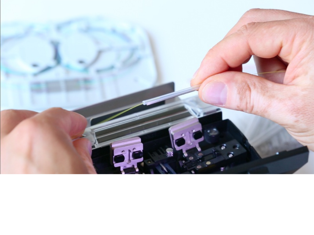
Step 3 - Clivage de la fibre
Positionner la fibre dans la rainure adaptée du guide fibre (250 ou 900 µm), la gaine 250 ou 900 µm à la graduation 10 en faisant attention que la partie dénuée prenne bien appui sur les 2 patins.


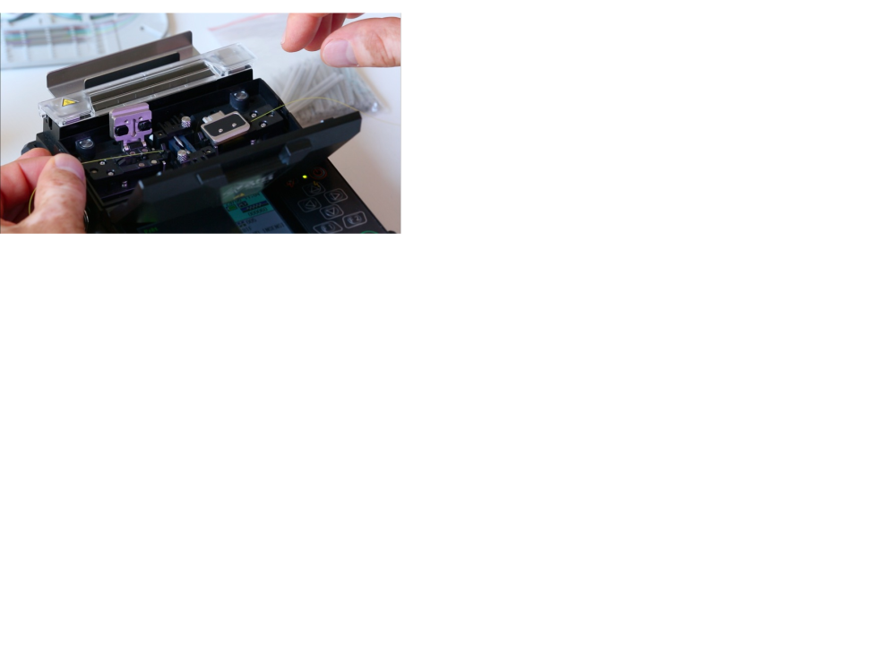
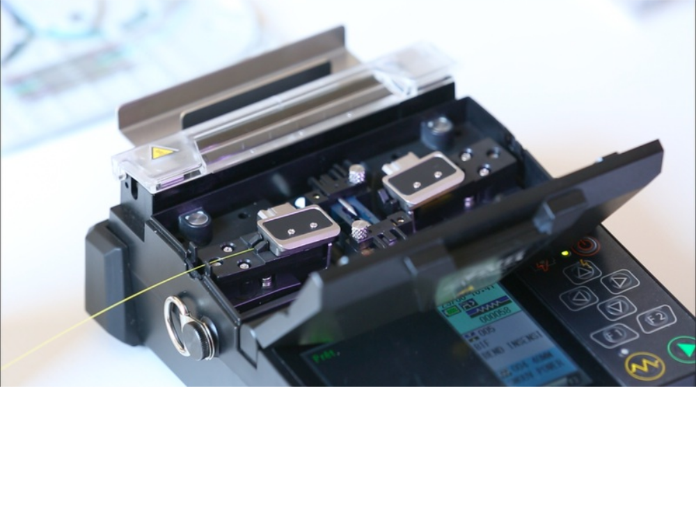
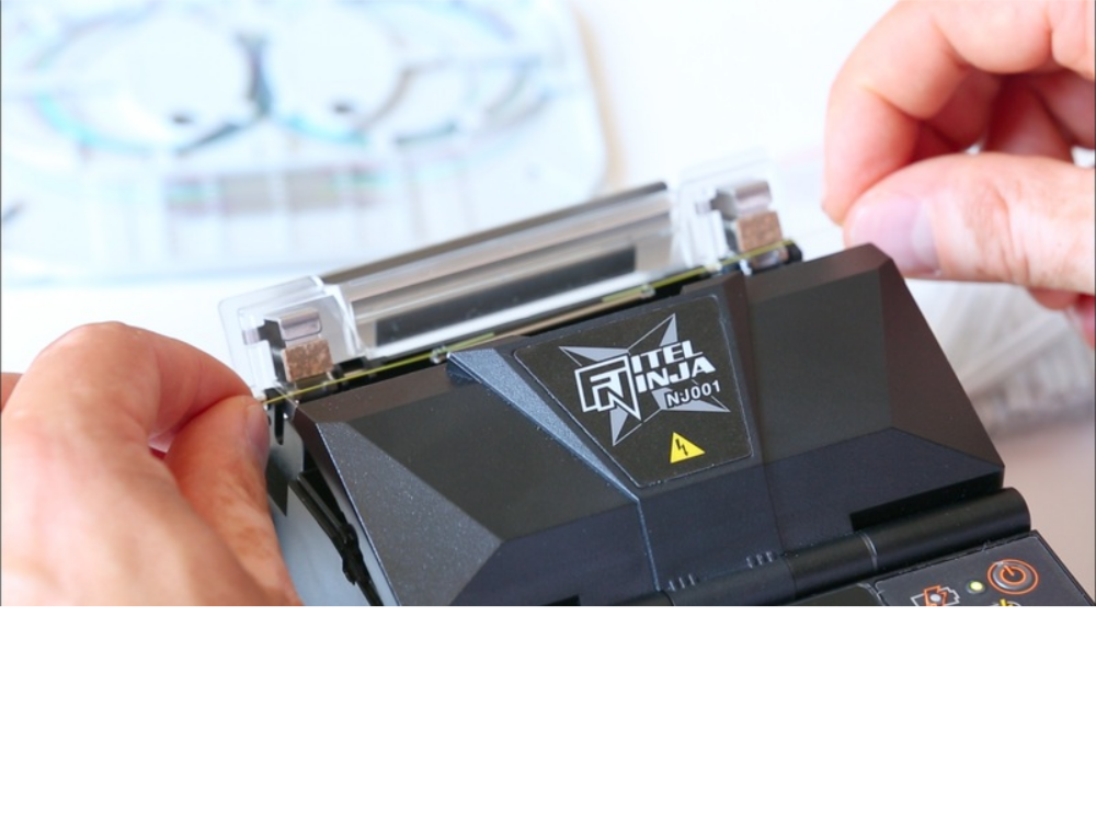
Step 4 - Positionnement de la fibre dans la soudeuse
Position the fibre in the fusion splicer by placing its end between the alignment of the electrodes and the edge of the V-slot, close the valve retaining the fibre.
NB: Be careful not to hit the end of the fibre as this may alter the quality of the cleavage.


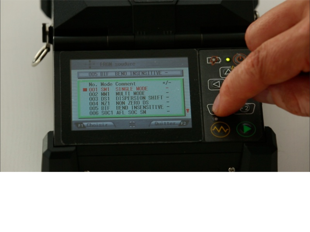
Step 5 - Choosing the programs of the welder machine
Use the welding program adapted to the type of fibre to be welded, as well as the furnace program adapted to the type of smoove used.
Example: Single mode MS, multi-mode MM and single mode BIF G657.


Step 6 - Welding process
Close the cover to initiate the welding process (the auto start function must be activated otherwise press the green arrow on the keyboard).


Step 7 - Welding evaluation
Three evaluation criteria should be observed: the image quality of the welded fibres (good alignment of the cores, absence of dust or air bubbles, etc.), the estimated loss given by the fusion splicer and the resistance of the fibre to the tensile test (not to be disabled).


Step 8 - Positioning the smoove and shrinkage
Before opening the cover, bring the smoove as close as possible to the fusion splicer, center it at the weld, making sure that the shrinkage will be on the fibre protection sheaths and not on the bare fibre. Position the smoove in the center of the furnace. The furnace is activated automatically if this function has been previously selected in the machine parameters, otherwise press the yellow resistance on the keyboard.


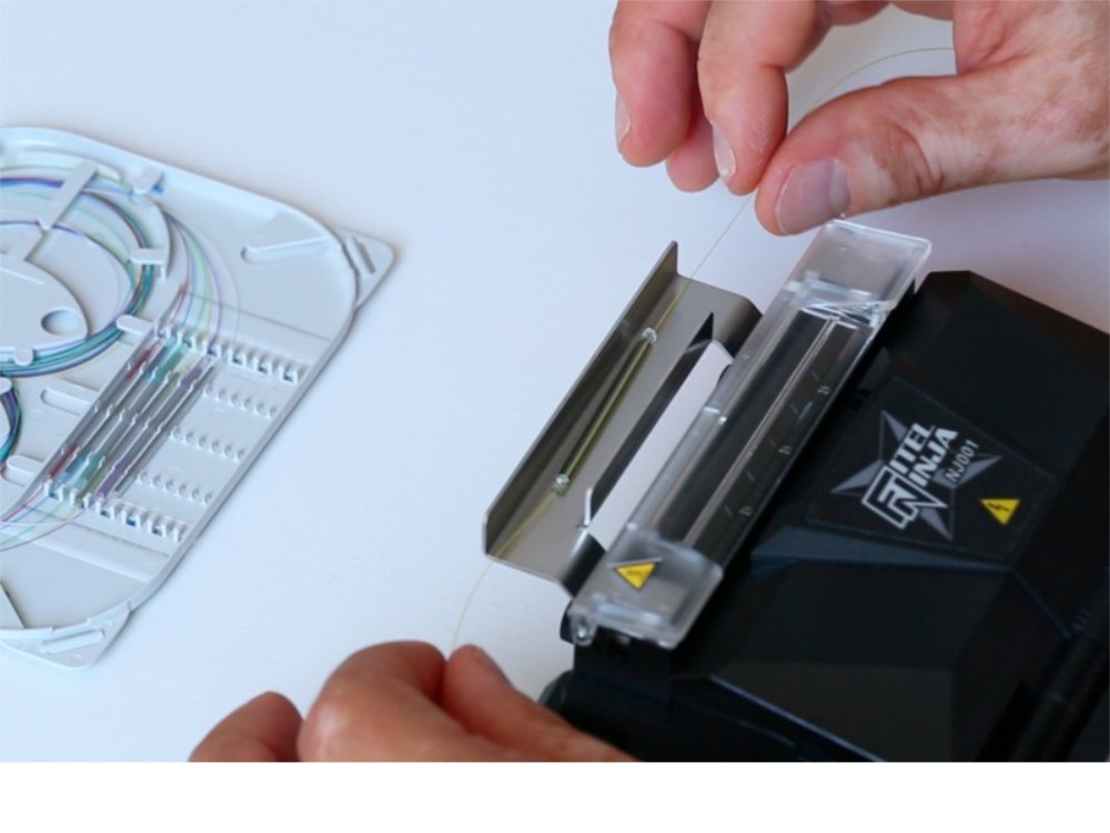
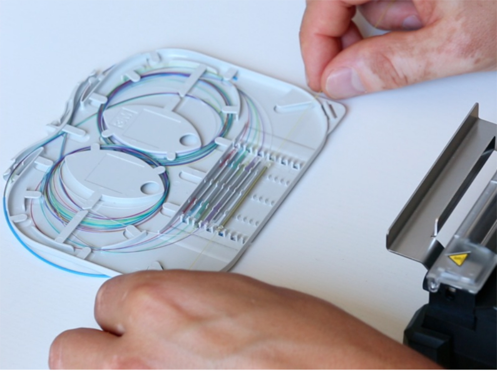
Step 9 - Positioning the smoove on a cassette for winding
After shrinking, position the smoove on the cooling plate before welding other fibres. Then place the smooves in the cassette and wind the fibres.
Published
 Français
 English
 Deutsch
 Español
 Italiano
 Português