| [pending review revision] | [pending review revision] |
(Cette version a été marquée pour être traduite) |
|||
| Line 2: | Line 2: | ||
|Main_Picture=Visual_location_of_defects_on_optical_fiber_img15.jpg | |Main_Picture=Visual_location_of_defects_on_optical_fiber_img15.jpg | ||
|Main_Picture_annotation={"version":"2.4.6","objects":[{"type":"image","version":"2.4.6","originX":"left","originY":"top","left":-12,"top":-2,"width":773,"height":530,"fill":"rgb(0,0,0)","stroke":null,"strokeWidth":0,"strokeDashArray":null,"strokeLineCap":"butt","strokeDashOffset":0,"strokeLineJoin":"miter","strokeMiterLimit":4,"scaleX":0.86,"scaleY":0.86,"angle":0,"flipX":false,"flipY":false,"opacity":1,"shadow":null,"visible":true,"clipTo":null,"backgroundColor":"","fillRule":"nonzero","paintFirst":"fill","globalCompositeOperation":"source-over","transformMatrix":null,"skewX":0,"skewY":0,"crossOrigin":"","cropX":0,"cropY":0,"src":"http://demo-master.dokit.io/w/images/a/a0/Visual_location_of_defects_on_optical_fiber_img15.jpg","filters":[]}],"height":449.7695852534562,"width":600} | |Main_Picture_annotation={"version":"2.4.6","objects":[{"type":"image","version":"2.4.6","originX":"left","originY":"top","left":-12,"top":-2,"width":773,"height":530,"fill":"rgb(0,0,0)","stroke":null,"strokeWidth":0,"strokeDashArray":null,"strokeLineCap":"butt","strokeDashOffset":0,"strokeLineJoin":"miter","strokeMiterLimit":4,"scaleX":0.86,"scaleY":0.86,"angle":0,"flipX":false,"flipY":false,"opacity":1,"shadow":null,"visible":true,"clipTo":null,"backgroundColor":"","fillRule":"nonzero","paintFirst":"fill","globalCompositeOperation":"source-over","transformMatrix":null,"skewX":0,"skewY":0,"crossOrigin":"","cropX":0,"cropY":0,"src":"http://demo-master.dokit.io/w/images/a/a0/Visual_location_of_defects_on_optical_fiber_img15.jpg","filters":[]}],"height":449.7695852534562,"width":600} | ||
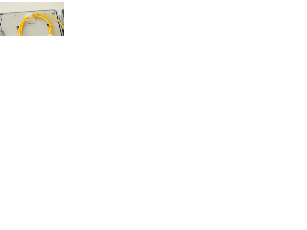
| − | |Description=<translate><!--T:1--> Locate a defect on an optical fiber and identify links thanks to the VFL TED Equipment.</translate> | + | |Description=<translate><!--T:1--> |
| + | Locate a defect on an optical fiber and identify links thanks to the VFL TED Equipment.</translate> | ||
|Categories=Work instructions | |Categories=Work instructions | ||
|Difficulty=Easy | |Difficulty=Easy | ||
| Line 20: | Line 21: | ||
}} | }} | ||
{{Tuto Step | {{Tuto Step | ||
| − | |Step_Title=<translate><!--T:2--> | + | |Step_Title=<translate><!--T:2--> |
| + | Safety rule</translate> | ||
|Step_Content=<translate><!--T:3--> | |Step_Content=<translate><!--T:3--> | ||
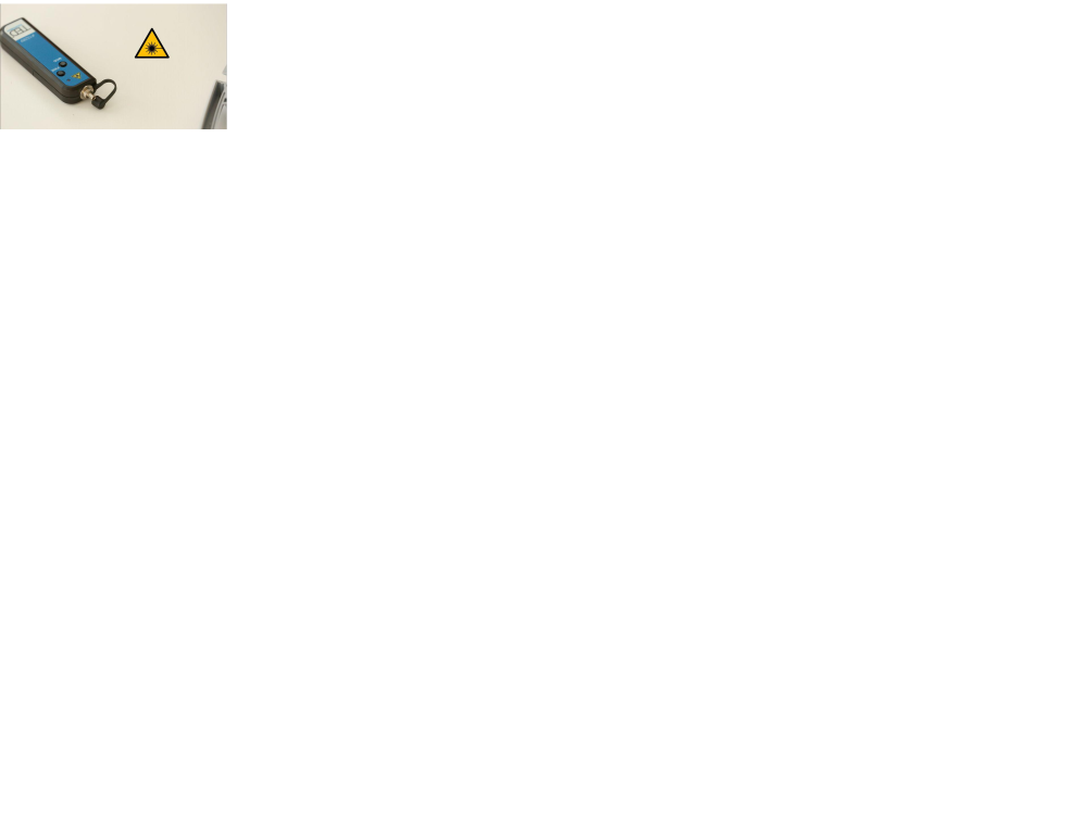
The visual defect locator (or optical pencil) emits red light at an output power of 10 mW. Do not directly look at the light beam or direct it at another person. Always replace the protective cap after use. | The visual defect locator (or optical pencil) emits red light at an output power of 10 mW. Do not directly look at the light beam or direct it at another person. Always replace the protective cap after use. | ||
| − | |||
<!--T:4--> | <!--T:4--> | ||
| Line 35: | Line 36: | ||
}} | }} | ||
{{Tuto Step | {{Tuto Step | ||
| − | |Step_Title=<translate><!--T:5--> | + | |Step_Title=<translate><!--T:5--> |
| − | |Step_Content=<translate><!--T:6--> Press the PWR button. The locator emits a continuous or pulsed signal depending on the setting selected with the MOD button.</translate> | + | Ignition and configuration</translate> |
| + | |Step_Content=<translate><!--T:6--> | ||
| + | Press the PWR button. The locator emits a continuous or pulsed signal depending on the setting selected with the MOD button.</translate> | ||
|Step_Picture_00=Visual_location_of_defects_on_optical_fiber_img73.jpg | |Step_Picture_00=Visual_location_of_defects_on_optical_fiber_img73.jpg | ||
|Step_Picture_00_annotation={"version":"2.4.6","objects":[{"type":"image","version":"2.4.6","originX":"left","originY":"top","left":-189,"top":-6,"width":800,"height":443,"fill":"rgb(0,0,0)","stroke":null,"strokeWidth":0,"strokeDashArray":null,"strokeLineCap":"butt","strokeDashOffset":0,"strokeLineJoin":"miter","strokeMiterLimit":4,"scaleX":1.03,"scaleY":1.03,"angle":0,"flipX":false,"flipY":false,"opacity":1,"shadow":null,"visible":true,"clipTo":null,"backgroundColor":"","fillRule":"nonzero","paintFirst":"fill","globalCompositeOperation":"source-over","transformMatrix":null,"skewX":0,"skewY":0,"crossOrigin":"","cropX":0,"cropY":0,"src":"http://demo-master.dokit.io/w/images/b/b7/Visual_location_of_defects_on_optical_fiber_img73.jpg","filters":[]}],"height":449.7131931166348,"width":600} | |Step_Picture_00_annotation={"version":"2.4.6","objects":[{"type":"image","version":"2.4.6","originX":"left","originY":"top","left":-189,"top":-6,"width":800,"height":443,"fill":"rgb(0,0,0)","stroke":null,"strokeWidth":0,"strokeDashArray":null,"strokeLineCap":"butt","strokeDashOffset":0,"strokeLineJoin":"miter","strokeMiterLimit":4,"scaleX":1.03,"scaleY":1.03,"angle":0,"flipX":false,"flipY":false,"opacity":1,"shadow":null,"visible":true,"clipTo":null,"backgroundColor":"","fillRule":"nonzero","paintFirst":"fill","globalCompositeOperation":"source-over","transformMatrix":null,"skewX":0,"skewY":0,"crossOrigin":"","cropX":0,"cropY":0,"src":"http://demo-master.dokit.io/w/images/b/b7/Visual_location_of_defects_on_optical_fiber_img73.jpg","filters":[]}],"height":449.7131931166348,"width":600} | ||
}} | }} | ||
{{Tuto Step | {{Tuto Step | ||
| − | |Step_Title=<translate><!--T:7--> | + | |Step_Title=<translate><!--T:7--> |
| − | |Step_Content=<translate><!--T:8--> The visual defect locator is compatible with all connectors with a 2.5 mm ferrule. For 1.25 mm ferrules, the use of an adapter is required.</translate> | + | Connection to the fibre</translate> |
| + | |Step_Content=<translate><!--T:8--> | ||
| + | The visual defect locator is compatible with all connectors with a 2.5 mm ferrule. For 1.25 mm ferrules, the use of an adapter is required.</translate> | ||
|Step_Picture_00=Visual_location_of_defects_on_optical_fiber_img88.jpg | |Step_Picture_00=Visual_location_of_defects_on_optical_fiber_img88.jpg | ||
|Step_Picture_00_annotation={"version":"2.4.6","objects":[{"type":"image","version":"2.4.6","originX":"left","originY":"top","left":-102,"top":-2,"width":800,"height":443,"fill":"rgb(0,0,0)","stroke":null,"strokeWidth":0,"strokeDashArray":null,"strokeLineCap":"butt","strokeDashOffset":0,"strokeLineJoin":"miter","strokeMiterLimit":4,"scaleX":1.03,"scaleY":1.03,"angle":0,"flipX":false,"flipY":false,"opacity":1,"shadow":null,"visible":true,"clipTo":null,"backgroundColor":"","fillRule":"nonzero","paintFirst":"fill","globalCompositeOperation":"source-over","transformMatrix":null,"skewX":0,"skewY":0,"crossOrigin":"","cropX":0,"cropY":0,"src":"http://demo-master.dokit.io/w/images/d/df/Visual_location_of_defects_on_optical_fiber_img88.jpg","filters":[]}],"height":449.4296577946768,"width":600} | |Step_Picture_00_annotation={"version":"2.4.6","objects":[{"type":"image","version":"2.4.6","originX":"left","originY":"top","left":-102,"top":-2,"width":800,"height":443,"fill":"rgb(0,0,0)","stroke":null,"strokeWidth":0,"strokeDashArray":null,"strokeLineCap":"butt","strokeDashOffset":0,"strokeLineJoin":"miter","strokeMiterLimit":4,"scaleX":1.03,"scaleY":1.03,"angle":0,"flipX":false,"flipY":false,"opacity":1,"shadow":null,"visible":true,"clipTo":null,"backgroundColor":"","fillRule":"nonzero","paintFirst":"fill","globalCompositeOperation":"source-over","transformMatrix":null,"skewX":0,"skewY":0,"crossOrigin":"","cropX":0,"cropY":0,"src":"http://demo-master.dokit.io/w/images/d/df/Visual_location_of_defects_on_optical_fiber_img88.jpg","filters":[]}],"height":449.4296577946768,"width":600} | ||
| Line 53: | Line 58: | ||
}} | }} | ||
{{Tuto Step | {{Tuto Step | ||
| − | |Step_Title=<translate><!--T:9--> | + | |Step_Title=<translate><!--T:9--> |
| − | |Step_Content=<translate><!--T:10--> The locator can be used on links up to 10 km. Beyond that, whatever the power of an optical pencil, the light beam cannot be perceived.</translate> | + | Identify the length of the fibre</translate> |
| + | |Step_Content=<translate><!--T:10--> | ||
| + | The locator can be used on links up to 10 km. Beyond that, whatever the power of an optical pencil, the light beam cannot be perceived.</translate> | ||
|Step_Picture_00=Visual_location_of_defects_on_optical_fiber_img96.jpg | |Step_Picture_00=Visual_location_of_defects_on_optical_fiber_img96.jpg | ||
|Step_Picture_00_annotation={"version":"2.4.6","objects":[{"type":"image","version":"2.4.6","originX":"left","originY":"top","left":-201,"top":-1,"width":800,"height":425,"fill":"rgb(0,0,0)","stroke":null,"strokeWidth":0,"strokeDashArray":null,"strokeLineCap":"butt","strokeDashOffset":0,"strokeLineJoin":"miter","strokeMiterLimit":4,"scaleX":1.07,"scaleY":1.07,"angle":0,"flipX":false,"flipY":false,"opacity":1,"shadow":null,"visible":true,"clipTo":null,"backgroundColor":"","fillRule":"nonzero","paintFirst":"fill","globalCompositeOperation":"source-over","transformMatrix":null,"skewX":0,"skewY":0,"crossOrigin":"","cropX":0,"cropY":0,"src":"http://demo-master.dokit.io/w/images/2/27/Visual_location_of_defects_on_optical_fiber_img96.jpg","filters":[]}],"height":450.2970297029703,"width":600} | |Step_Picture_00_annotation={"version":"2.4.6","objects":[{"type":"image","version":"2.4.6","originX":"left","originY":"top","left":-201,"top":-1,"width":800,"height":425,"fill":"rgb(0,0,0)","stroke":null,"strokeWidth":0,"strokeDashArray":null,"strokeLineCap":"butt","strokeDashOffset":0,"strokeLineJoin":"miter","strokeMiterLimit":4,"scaleX":1.07,"scaleY":1.07,"angle":0,"flipX":false,"flipY":false,"opacity":1,"shadow":null,"visible":true,"clipTo":null,"backgroundColor":"","fillRule":"nonzero","paintFirst":"fill","globalCompositeOperation":"source-over","transformMatrix":null,"skewX":0,"skewY":0,"crossOrigin":"","cropX":0,"cropY":0,"src":"http://demo-master.dokit.io/w/images/2/27/Visual_location_of_defects_on_optical_fiber_img96.jpg","filters":[]}],"height":450.2970297029703,"width":600} | ||
| Line 61: | Line 68: | ||
}} | }} | ||
{{Tuto Step | {{Tuto Step | ||
| − | |Step_Title=<translate><!--T:11--> | + | |Step_Title=<translate><!--T:11--> |
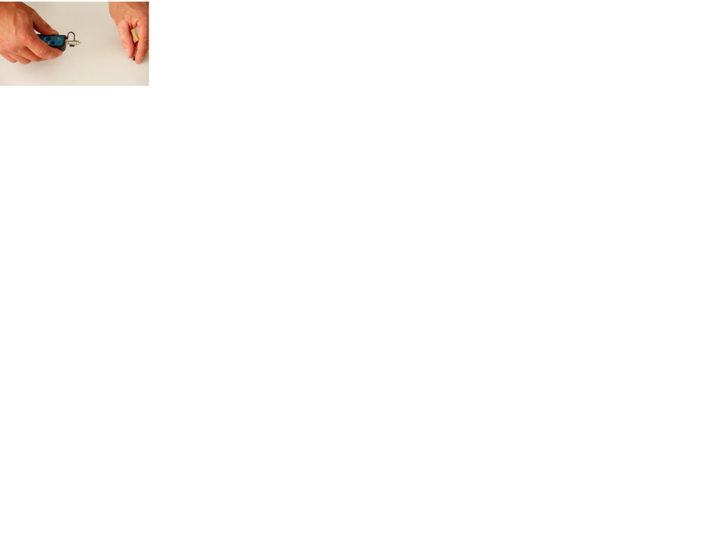
| − | |Step_Content=<translate><!--T:12--> The end of an optical link is detected by the presence of the light signal. This is a function widely used for mixing garters in street cabinets or bays.</translate> | + | Locating the end</translate> |
| + | |Step_Content=<translate><!--T:12--> | ||
| + | The end of an optical link is detected by the presence of the light signal. This is a function widely used for mixing garters in street cabinets or bays.</translate> | ||
|Step_Picture_00=Visual_location_of_defects_on_optical_fiber_img100.jpg | |Step_Picture_00=Visual_location_of_defects_on_optical_fiber_img100.jpg | ||
|Step_Picture_00_annotation={"version":"2.4.6","objects":[{"type":"image","version":"2.4.6","originX":"left","originY":"top","left":-188,"top":-1,"width":800,"height":413,"fill":"rgb(0,0,0)","stroke":null,"strokeWidth":0,"strokeDashArray":null,"strokeLineCap":"butt","strokeDashOffset":0,"strokeLineJoin":"miter","strokeMiterLimit":4,"scaleX":1.1,"scaleY":1.1,"angle":0,"flipX":false,"flipY":false,"opacity":1,"shadow":null,"visible":true,"clipTo":null,"backgroundColor":"","fillRule":"nonzero","paintFirst":"fill","globalCompositeOperation":"source-over","transformMatrix":null,"skewX":0,"skewY":0,"crossOrigin":"","cropX":0,"cropY":0,"src":"http://demo-master.dokit.io/w/images/5/58/Visual_location_of_defects_on_optical_fiber_img100.jpg","filters":[]}],"height":449.69450101832996,"width":600} | |Step_Picture_00_annotation={"version":"2.4.6","objects":[{"type":"image","version":"2.4.6","originX":"left","originY":"top","left":-188,"top":-1,"width":800,"height":413,"fill":"rgb(0,0,0)","stroke":null,"strokeWidth":0,"strokeDashArray":null,"strokeLineCap":"butt","strokeDashOffset":0,"strokeLineJoin":"miter","strokeMiterLimit":4,"scaleX":1.1,"scaleY":1.1,"angle":0,"flipX":false,"flipY":false,"opacity":1,"shadow":null,"visible":true,"clipTo":null,"backgroundColor":"","fillRule":"nonzero","paintFirst":"fill","globalCompositeOperation":"source-over","transformMatrix":null,"skewX":0,"skewY":0,"crossOrigin":"","cropX":0,"cropY":0,"src":"http://demo-master.dokit.io/w/images/5/58/Visual_location_of_defects_on_optical_fiber_img100.jpg","filters":[]}],"height":449.69450101832996,"width":600} | ||
}} | }} | ||
{{Tuto Step | {{Tuto Step | ||
| − | |Step_Title=<translate><!--T:13--> | + | |Step_Title=<translate><!--T:13--> |
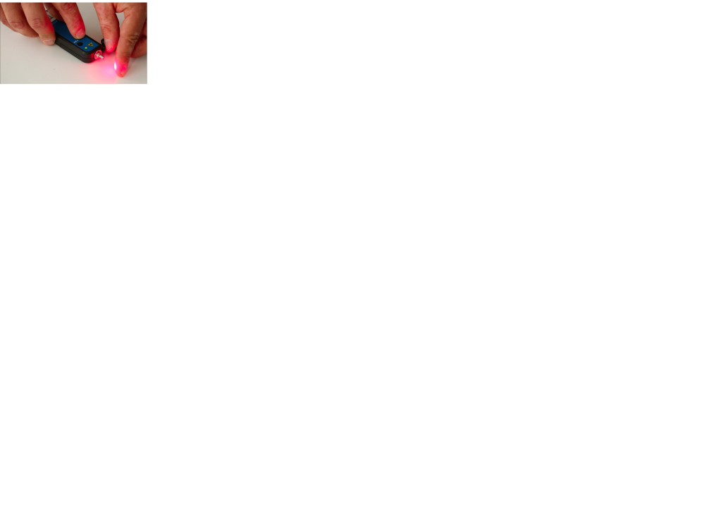
| − | |Step_Content=<translate><!--T:14--> Due to the high reflection of the light as it passes through a stress (macro-curve) or when a fibre is cut, this device is widely used to correct defects (which cause significant optical losses), on the visible part of the fibres.</translate> | + | Locating the defect (a curve for example)</translate> |
| + | |Step_Content=<translate><!--T:14--> | ||
| + | Due to the high reflection of the light as it passes through a stress (macro-curve) or when a fibre is cut, this device is widely used to correct defects (which cause significant optical losses), on the visible part of the fibres.</translate> | ||
|Step_Picture_00=Visual_location_of_defects_on_optical_fiber_img120.jpg | |Step_Picture_00=Visual_location_of_defects_on_optical_fiber_img120.jpg | ||
|Step_Picture_00_annotation={"version":"2.4.6","objects":[{"type":"image","version":"2.4.6","originX":"left","originY":"top","left":-41,"top":-3,"width":800,"height":444,"fill":"rgb(0,0,0)","stroke":null,"strokeWidth":0,"strokeDashArray":null,"strokeLineCap":"butt","strokeDashOffset":0,"strokeLineJoin":"miter","strokeMiterLimit":4,"scaleX":1.03,"scaleY":1.03,"angle":0,"flipX":false,"flipY":false,"opacity":1,"shadow":null,"visible":true,"clipTo":null,"backgroundColor":"","fillRule":"nonzero","paintFirst":"fill","globalCompositeOperation":"source-over","transformMatrix":null,"skewX":0,"skewY":0,"crossOrigin":"","cropX":0,"cropY":0,"src":"http://demo-master.dokit.io/w/images/a/a7/Visual_location_of_defects_on_optical_fiber_img120.jpg","filters":[]}],"height":450.2857142857143,"width":600} | |Step_Picture_00_annotation={"version":"2.4.6","objects":[{"type":"image","version":"2.4.6","originX":"left","originY":"top","left":-41,"top":-3,"width":800,"height":444,"fill":"rgb(0,0,0)","stroke":null,"strokeWidth":0,"strokeDashArray":null,"strokeLineCap":"butt","strokeDashOffset":0,"strokeLineJoin":"miter","strokeMiterLimit":4,"scaleX":1.03,"scaleY":1.03,"angle":0,"flipX":false,"flipY":false,"opacity":1,"shadow":null,"visible":true,"clipTo":null,"backgroundColor":"","fillRule":"nonzero","paintFirst":"fill","globalCompositeOperation":"source-over","transformMatrix":null,"skewX":0,"skewY":0,"crossOrigin":"","cropX":0,"cropY":0,"src":"http://demo-master.dokit.io/w/images/a/a7/Visual_location_of_defects_on_optical_fiber_img120.jpg","filters":[]}],"height":450.2857142857143,"width":600} | ||
| Line 75: | Line 86: | ||
}} | }} | ||
{{Tuto Step | {{Tuto Step | ||
| − | |Step_Title=<translate><!--T:15--> | + | |Step_Title=<translate><!--T:15--> |
| − | |Step_Content=<translate><!--T:16--> After using the device, turn off the locator and place the protective cap on the optical output.</translate> | + | Turn off the device</translate> |
| + | |Step_Content=<translate><!--T:16--> | ||
| + | After using the device, turn off the locator and place the protective cap on the optical output.</translate> | ||
|Step_Picture_00=Visual_location_of_defects_on_optical_fiber_img124.jpg | |Step_Picture_00=Visual_location_of_defects_on_optical_fiber_img124.jpg | ||
|Step_Picture_00_annotation={"version":"2.4.6","objects":[{"type":"image","version":"2.4.6","originX":"left","originY":"top","left":-78,"top":-2,"width":800,"height":441,"fill":"rgb(0,0,0)","stroke":null,"strokeWidth":0,"strokeDashArray":null,"strokeLineCap":"butt","strokeDashOffset":0,"strokeLineJoin":"miter","strokeMiterLimit":4,"scaleX":1.04,"scaleY":1.04,"angle":0,"flipX":false,"flipY":false,"opacity":1,"shadow":null,"visible":true,"clipTo":null,"backgroundColor":"","fillRule":"nonzero","paintFirst":"fill","globalCompositeOperation":"source-over","transformMatrix":null,"skewX":0,"skewY":0,"crossOrigin":"","cropX":0,"cropY":0,"src":"http://demo-master.dokit.io/w/images/9/9c/Visual_location_of_defects_on_optical_fiber_img124.jpg","filters":[]}],"height":450.2879078694818,"width":600} | |Step_Picture_00_annotation={"version":"2.4.6","objects":[{"type":"image","version":"2.4.6","originX":"left","originY":"top","left":-78,"top":-2,"width":800,"height":441,"fill":"rgb(0,0,0)","stroke":null,"strokeWidth":0,"strokeDashArray":null,"strokeLineCap":"butt","strokeDashOffset":0,"strokeLineJoin":"miter","strokeMiterLimit":4,"scaleX":1.04,"scaleY":1.04,"angle":0,"flipX":false,"flipY":false,"opacity":1,"shadow":null,"visible":true,"clipTo":null,"backgroundColor":"","fillRule":"nonzero","paintFirst":"fill","globalCompositeOperation":"source-over","transformMatrix":null,"skewX":0,"skewY":0,"crossOrigin":"","cropX":0,"cropY":0,"src":"http://demo-master.dokit.io/w/images/9/9c/Visual_location_of_defects_on_optical_fiber_img124.jpg","filters":[]}],"height":450.2879078694818,"width":600} | ||
Latest revision as of 15:51, 7 June 2019


- Items
Items

Step 1 - Safety rule
The visual defect locator (or optical pencil) emits red light at an output power of 10 mW. Do not directly look at the light beam or direct it at another person. Always replace the protective cap after use.
Switch on the unit only when the protective cap is in place or a connector is attached to the outlet.

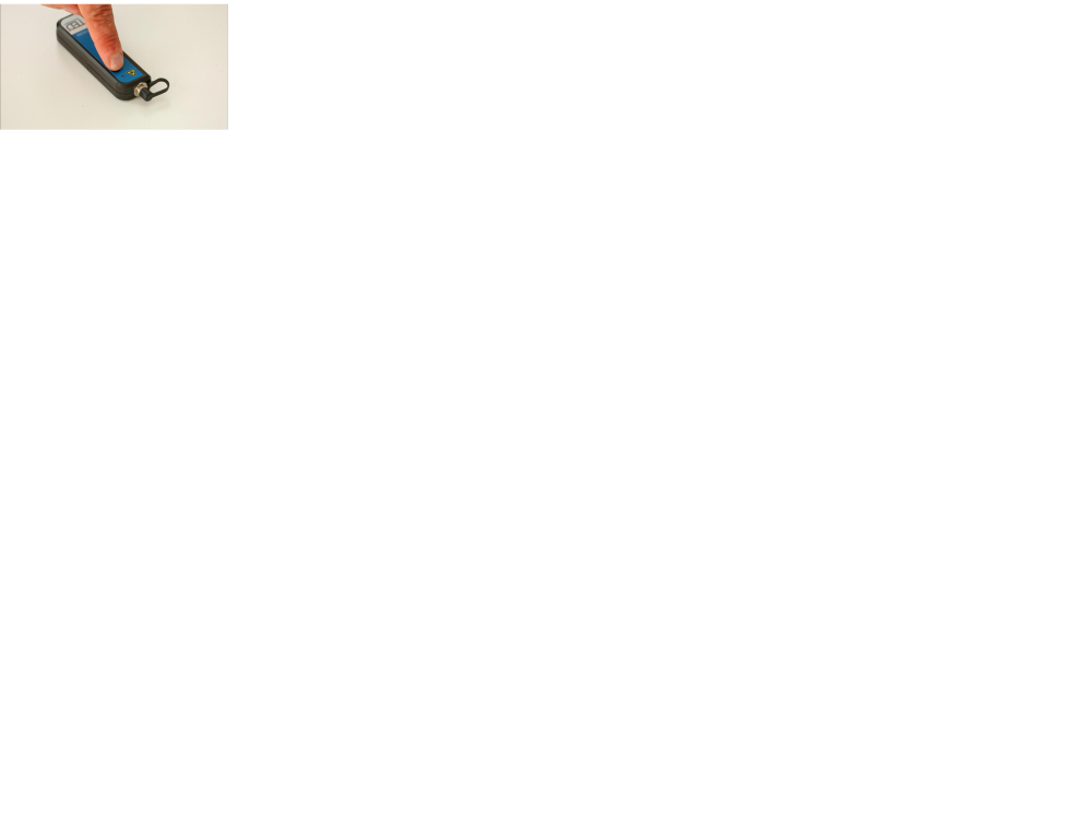
Step 2 - Ignition and configuration
Press the PWR button. The locator emits a continuous or pulsed signal depending on the setting selected with the MOD button.
Step 3 - Connection to the fibre
The visual defect locator is compatible with all connectors with a 2.5 mm ferrule. For 1.25 mm ferrules, the use of an adapter is required.


Step 4 - Identify the length of the fibre
The locator can be used on links up to 10 km. Beyond that, whatever the power of an optical pencil, the light beam cannot be perceived.

Step 5 - Locating the end
The end of an optical link is detected by the presence of the light signal. This is a function widely used for mixing garters in street cabinets or bays.

Step 6 - Locating the defect (a curve for example)
Due to the high reflection of the light as it passes through a stress (macro-curve) or when a fibre is cut, this device is widely used to correct defects (which cause significant optical losses), on the visible part of the fibres.


Step 7 - Turn off the device
After using the device, turn off the locator and place the protective cap on the optical output.

Published
 Français
 English
 Deutsch
 Español
 Italiano
 Português